While the Redbird 1000 is designed to look and operate like a Garmin G1000, it does not model all the features of the Garmin G1000 -- although, new features are added frequently. The Redbird 1000 models most of what a typical private pilot would use on a typical VFR or IFR flight (using an early model G1000). While this supplement discusses the basics of operating this device, the most comprehensive guide is available for download from Garmin’s website.
Available Features: PFD | MFD | Audio Panel | General Operations | Failure Modes
Basic Operations: Controls and Keys | Indicators | NAV/COM | PFD | MFD | Direct-to Navigation
Please Note
The reader of this manual is expected to know how to fly an aircraft or to be participating in a structured and approved flight training program. This manual is in no respect a tutorial in visual flight, instrument flight, or navigation. Its only purpose is to introduce the hardware and software to enable a pilot to use the system.
The information in this manual is subject to change without notice and does not represent a commitment on the part of the licensor. The software and hardware described in this document are provided under a license agreement. The software and hardware may be used or copied only in accordance with the terms of the license agreement.
Available Features
Primary Flight Display - PFD
| Feature | Available Now | Future Development | ||
| Nav Radio Tuning Cursor | ✅ | |||
| Nav Radio Volume | ☑️ | |||
| Nav Radio Morse ID | ✅ | |||
| Nav Radio Frequency Toggle | ✅ | |||
| Nav Radio Knob Push-to-Select | ✅ | |||
| Nav Radio Inner/Outer Tuning Knob | ✅ | |||
| ADF Radio Tuning and RMI Pointer | ✅ | |||
| DME Window on HSI | ✅ | |||
|
Heading Bug Course Selector Knob |
✅ | |||
| Heading Knob Push-to-Sync | ✅ | |||
|
Airspeed Bugs on Airspeed Tape |
✅ | |||
|
Altitude Bug Selector |
✅ | |||
|
COM Volume/Squelch |
☑️ | |||
| COM Radio Frequency Toggle | ✅ | |||
| COM Radio Auto-Tune 121.5 | ✅ | |||
| COM Radio Inner/outer Tuning Knobs | ✅ | |||
| BARO Pressure Selector Knob | ✅ | |||
| CRS Selector Knob | ✅ | |||
| CRS Knob Push-to-Sync | ✅ | |||
| Range Knob (Inset Map Zoom) | ✅ | |||
| Range Knob Push-for-Cursor | ✅ | |||
| GPS Direct-To Button on PFD | ✅ | |||
| GPS FPL Flight Plan Button on PFD | ✅ | |||
| GPS CLR Button on PFD | ✅ | |||
| GPS Menu Button on PFD | ✅ | |||
| PROC Inst Procedures Button on PFD | ✅ | |||
| Select/Display Instrument Approaches | ✅ | |||
| FMS Inner/Outer Knobs | ✅ | |||
| PFD Inset Map | ✅ | |||
| Traffic Display on Inset Map | ✅ | |||
| TOPO Display on Inset Map (formerly called "terrain" in GNS530) |
✅ | |||
| Terrain Display on Inset Map (refers to TAWS-style display on map) |
✅ | |||
| Flight Plan Display on Inset Map | ✅ | |||
| Airspace & Waypoints on Inset Map | ✅ | |||
| Zoom Scale Indicator on Inset Map | ✅ | |||
| Transponder Code Softkeys | ✅ | |||
| Transponder Mode Softkeys | ✅ | |||
| Transponder IDENT Softkey | ☑️ | |||
| NRST Softkey | ✅ | |||
| DCLTR De-clutter Softkey | ✅ | |||
| CDI Selector Softkey | ✅ | |||
| Current Time Display | ✅ | |||
| Alerts & Warnings Expanded Window | ✅ | |||
| Annunciations Window | ✅ | |||
| Active Waypoint Name | ✅ | |||
| Active Waypoint Distance | ✅ | |||
| Active Waypoint Desired Track DTK | ✅ | |||
| Active Waypoint Actual Track TRK | ✅ | |||
| Basic Airspeed Indicator Tape | ✅ | |||
| Airspeed Range "Arc" Colors | ✅ | |||
| True Airspeed Indicator | ✅ | |||
| Bank Scale | ✅ | |||
| Pitch Scale | ✅ | |||
| HSI | ✅ | |||
| Rate-of-turn "Arc" on HSI | ✅ | |||
| PFD Bearing (RMI) Indicators | ✅ | |||
| Basic Altimeter Tape | ✅ | |||
| Kohlsman Window (Baro) | ✅ | |||
| Vertical Speed Indicator | ✅ | |||
| ILS Glideslope Indicator | ✅ | |||
| OMI Marker Beacon Indicator | ✅ | |||
| Wind Vector Window | ✅ | |||
| Set Minimums in TMR/REF Window | ✅ | |||
| Show Minimums mark in altimeter tape | ✅ | |||
| Minimums audible annunciation | ✅ | |||
| Show Minimums popup display window | ✅ | |||
| GFC-700 autopilot option | ✅ | |||
| VNAV VPTH/ALTV mode | ✅ | |||
| Vertical Track annunciation | ✅ |
Multi-Function Display - MFD
| Feature | Available Now | Future Development | ||
| Nav Radio Tuning Cursor | ✅ | |||
| Nav Radio Volume | ☑️ | |||
| Nav Radio Morse ID | ✅ | |||
| Nav Radio Frequency Toggle | ✅ | |||
| Nav Radio Knob Push-to-Select | ✅ | |||
| Nav Radio Inner/Outer Tuning Knob | ✅ | |||
| Heading Bug Course Selector Knob | ✅ | |||
| Heading Knob Push-to-Sync | ✅ | |||
| Altitude Bug Selector | ✅ | |||
| COM Volume/Squelch | ☑️ | |||
| COM Radio Frequency Toggle | ✅ | |||
| COM Radio Auto-Tune 121.5 | ✅ | |||
| COM Radio Inner/outer Tuning Knobs | ✅ | |||
| BARO Pressure Selector Knob | ✅ | |||
| CRS Selector Knob | ✅ | |||
| CRS Knob Push-to-Sync | ✅ | |||
| Range Knob (Inset Map Zoom) | ✅ | |||
| Range Knob Push-for-Cursor | ✅ | |||
| GPS Direct-To Button on MFD | ✅ | |||
| GPS FPL Flight Plan Button on MFD | ✅ | |||
| GPS CLR Button on MFD | ✅ | |||
| GPS Menu Button on MFD | ✅ | |||
| PROC Inst Procedures Button on MFD | ✅ | |||
| Main MFD Moving Map | ✅ | |||
| Traffic Display on MFD Main Map | ✅ | |||
| TOPO Display on MFD Main Map (formerly called "terrain" in GNS530) |
✅ | |||
| Terrain Display on MFD Main Map (refers to TAWS-style display on map) |
✅ | |||
| Flight Plan Display on MFD Main Map | ✅ | |||
| Airspace & Waypoints on MFD Map | ✅ | |||
| Zoom Scale Indicator on MFD Map | ✅ | |||
| North Pointer on MFD Map | ✅ | |||
| Track-Up / North-Up Selection | ✅ | |||
| Wind Vector Indicator | ✅ | |||
| VOR Radial Display | ✅ | |||
| FMS Page Group and Page Selector | ✅ | |||
| MAP Group Traffic Page | ✅ | |||
| MAP Group Terrain Page | ☑️ | |||
| WPT Group Airport Lookup Page | ✅ | |||
| WPT Group NDB Lookup Page | ✅ | |||
| WPT Group VOR Lookup Page | ✅ | |||
| WPT Group Intersection Lookup Page | ✅ | |||
| WPT Group User Waypoint Page | ✅ | |||
| AUX Page Group, All Pages | ✅ | |||
| NRST Airports List | ✅ | |||
| NRST Intersections List | ✅ | |||
| NRST NDBs List | ✅ | |||
| NRST VORs List | ✅ | |||
| NRST User Waypoint List | ✅ | |||
| NRST ARTCC List | ✅ | |||
| NRST Airspace List | ✅ | |||
| FPL Page Group, All Pages (includes loading & saving of flight plans) |
✅ | |||
| Engine Manifold Pressure Indicator | ✅ | |||
| Engine RPM Indicator | ✅ | |||
| Fuel Flow GPH Indicator | ✅ | |||
| Engine Cylinder Head Temp Indicator | ✅ | |||
| Engine Oil Temp Indicator | ✅ | |||
| Engine Oil Pressure Indicator | ✅ | |||
| Electrical System Amps Indicator | ✅ | |||
| Fuel Quantity Indicator | ✅ | |||
| Engine Lean Assist | ✅ | |||
| VNAV altitudes in FPL (for GFC-700) | ✅ | |||
| ADF Dip | ✅ |
Audio Panel
| Feature | Available Now | Future Development | ||
| Transmit COM1 | ✅ | |||
| Transmit COM2 | ✅ | |||
| Monitor COM1 | ✅ | |||
| Monitor COM2 | ✅ | |||
| Reversionary Mode | ✅ | |||
| Marker mute | ✅ |
General Operations
| Feature | Available Now | Future Development |
| Save Flight Plans | ✅ | |
| Keypad (in applicable airframes) |
✅ | |
| Autpilot Console (in applicable airframes) |
✅ |
Failure Modes
| Feature | Available Now | Future Development | ||
| AHRS failure | ✅ | |||
| ADC failure | ✅ | |||
| IAU failure | ✅ | |||
| EAU failure | ✅ | |||
| XPDR failure | ✅ | |||
| PFD failure | ✅ | |||
| MFD failure | ✅ | |||
| PFD-2 failure (in applicable airframes) |
✅ | |||
| COM failure | ✅ | |||
| NAV failure | ✅ | |||
| Glideslope failure | ✅ | |||
| RAIM failure | ✅ | |||
| TAWS failure | ✅ | |||
| AP Controller failure (GFC-700 Only) |
✅ | |||
| AP Servos failure (GFC-700 Only) |
✅ | |||
| DME failure | ✅ | |||
| Mistrim Failures (Elev/Rud/Aileron) | ✅ | |||
| Traffic (TIS) Failure | ✅ |
Want to request a feature? Contact Redbird Support and let us know.
Basic Operations
Controls and Keys
The PFD and the MFD both feature the same controls and keys, which have been designed to minimize your workload as you access the 1000's sophisticated functionality.

Knobs 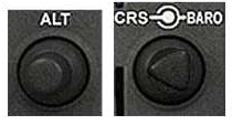
The Redbird 1000 includes two types of adjustment knobs: single knobs and dual knobs. Dual knobs have a large inner knob with a small outer knob on top of it.
Softkeys 
Softkeys are keys that can be reconfigured via software to do different things in different situations. One button can serve multiple purposes. Softkeys along the bottom of both the PFD and MFD provide you with access to numerous functions and pages in the 1000. If there is text above a softkey button, then it is an active softkey, and pressing the button will have an effect.
Note: To return to a previous level of softkeys press the BACK softkey.
Primary Flight Display 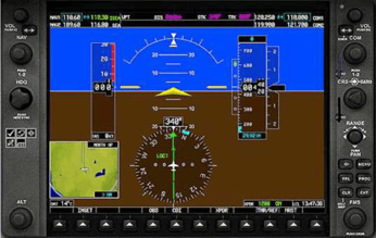
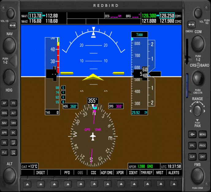
The Primary Flight Display (PFD) provides all the information displayed on a traditional airspeed indicator, attitude indicator, altimeter, vertical speed indicator, horizontal situation indicator, and turn coordinator in a modern, easy-to-scan format featuring a large horizon that's easy to see. The PFD also displays communication and navigational radio information, flight plan data, an inset moving map, outside air temperature, transponder status, and time of day.
NAV Frequency Window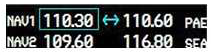
The Navigation (NAV) frequency window displays active and standby frequencies for dual VOR/ILS receivers (NAV1 and NAV2), as well as the identifier of a valid, identified navigation aid. The active frequency of each radio is on the right and the standby frequency is on the left. The cyan colored tuning box indicates which standby frequency will be set using the NAV knob.

To swap the standby NAV frequency and the active NAV frequency, press the
NAV Frequency Toggle key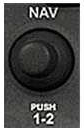
To tune the standby frequencies for the NAV receivers, rotate the NAV Frequency Selector knob. The big knob tunes MHz and the small knob tunes kHz. To toggle the cyan-colored tuning box between the NAV1 and NAV2 fields, press the small knob.
Navigation Status Bar

The Navigation Status Bar displays flight plan information when flying a route created using the Flight Planner or the 1000 Direct-to function:
- Next waypoint
- Navigation annunciations
- Distance to the next waypoint (DIS)
- Desired track to the next waypoint (DTK)
- Current track (TRK)
COM Frequency Window 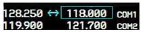
The Communication (COM) frequency window displays active and standby frequencies for dual VHF transceivers (COM1 and COM2). The active frequency of each radio is on the left and the standby frequency is on the right. The cyan-colored tuning box indicates which standby frequency will be set using the COM knob.
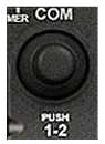
To tune the standby frequencies for the COM receivers, rotate the COM Frequency Selector knob. The big knob tunes MHz and the small knob tunes kHz. To toggle the cyan-colored tuning box between the COM1 and COM2 fields, press the small knob.
 To swap the standby COM frequency and the active COM frequency, press the COM Frequency Toggle key.
Airspeed indicator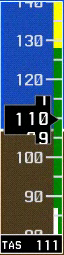
The Airspeed Indicator displays airspeed on a moving tape. The speed is displayed both numerically and as tick marks on the tape, and speed ranges are shown on a color-coded strip. An airspeed trend vector (magenta line) on the right side of the airspeed tape indicates the approximate airspeed that will be reached in six seconds given any aircraft acceleration.
Vspeed References (set using the TMR/REF softkey) make it easy to fly specific speeds like best glide, best angle of climb, and best rate of climb. The aircraft's true airspeed (indicated airspeed corrected for non-standard temperature and pressure) is displayed below the airspeed tape.
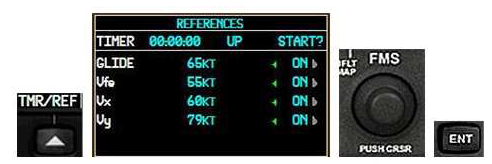
To change Vspeeds and turn the Vspeeds bug on or off:
- Press the TMR/REF softkey.
- Rotate the large FMS knob to highlight the Vspeed field.
- Rotate the small FMS knob to select the desired speed, and then press
the ENT key. (An asterisk appears to indicate you changed the default
speed.) - Rotate the large FMS knob to move the cursor to the Off/On field.
- Rotate the small FMS knob to select Off or On, and then press the ENT key.
- Press the TMR/REF softkey to close the window.
Attitude Indicator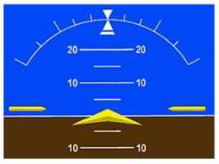
The aircraft's attitude relative to the horizon is displayed via the large blue sky, brown ground, and white horizon line that extends the width of the PFD. The Attitude Indicator indicates degrees of pitch and degrees of roll.
Slip/Skid Indicator![]()
The Slip/Skid Indicator is the small bar under the Roll Pointer. It moves away from the Roll Pointer to indicate slip or skid, just like the ball on a traditional Turn Coordinator.
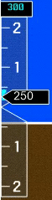
Altimeter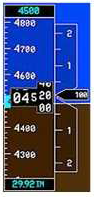
The Altimeter displays barometric altitude in feet on a moving tape. The altitude is displayed both numerically and as tick marks on the tape. An altitude trend vector (magenta line) on the left side of the altitude tape indicates the approximate altitude that will be reached in six seconds given the current vertical speed.
A reference altitude can be set in the box above the altitude tape, and a bug on the altitude tape indicates the reference altitude. The selected barometric pressure is displayed below the altitude tape.
To set the Altitude Reference bug rotate the ALT knob. The large knob sets thousands of feet and small ALT knob sets hundreds of feet.
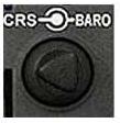 To set the altimeter barometric pressure rotate the large BARO knob.
When an ILS is tuned in the active NAV radio, a Vertical Deviation/Glide slope Indicator appears on the left side of the altimeter. A green diamond indicates vertical deviation (like a glide slope needle). Marker beacon annunciations are displayed to the left of the altitude reference box.
Vertical Speed Indicator
The Vertical Speed Indicator is to the right of the altitude tape. A pointer
indicates the aircraft's vertical speed in hundreds of feet.
Horizontal Situation Indicator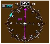
The Horizontal Situation Indicator (HSI) displays a rotating compass card with the aircraft's current heading at the top. A heading bug on the compass rose can be set to a desired heading, and the selected heading appears in a box to the left of the HSI.
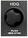
To set the Heading bug, rotate the Heading Selector knob or press the Heading Selector knob to synchronize with the aircraft's current heading.
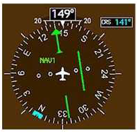
Desired navigational course is indicated by a course pointer arrow just like a traditional HSI, and the selected course appears to the right of the HSI. The Course Deviation Indicator (CDI) moves to the left or right of the course pointer to indicate the aircraft's position relative to the course.
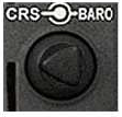
To set a course (NAV1 & NAV2 modes only), rotate the small CRS knob to the desired course.

To change navigation sources, press the CDI softkey to toggle between GPS, NAV1, NAV2, LOC1, and LOC2 (if a valid frequency is tuned).
Turn Rate Indicator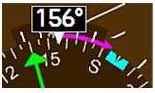
The Turn Rate Indicator is located above the rotating compass card on the HSI. A magenta trend vector indicates the heading predicted in six seconds given the current turn rate. Tick marks indicate standard and half-standard rate turns.
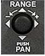
Inset Map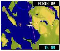
The Inset Map is a smaller version of the Navigation Map on the MFD. Range can be set independently of the MFD Map.

To display/hide the Inset Map press the INSET softkey.
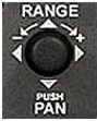
To change the Inset Map scale rotate the PFD Joystick knob.
To de-clutter the Inset Map
- Press the INSET softkey
- Press the DCLTR softkey
Outside Air Temperature
The outside air temperature is displayed in degrees Celsius at the bottom left of the PFD.
Transponder Status
The selected transponder code is displayed in a box at the bottom right of the PFD.
To select a transponder code:
- Press the XPDR softkey, then press the CODE
softkey and enter a code using the
number softkeys. - Press the VFR softkey to enter 1200.
- Press the BACK softkey to return to the top level.
Local Time
The local time (LCL) is displayed to the right of the Transponder Status box.
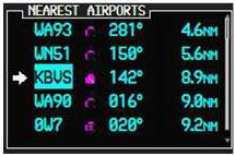
Nearest Airports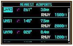
Want to quickly navigate to one of the airports closest to your present position? Just press the NRST softkey, and the Nearest Airports window will display above the Transponder Status and Local Time boxes.
To navigate directly to one of the nearest airports: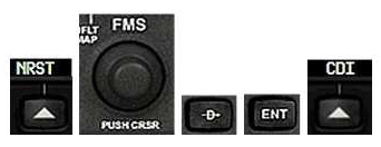
- Press the NRST softkey
- Turn the FMS knob to highlight the desired airport, then press the Direct-to key. The Direct-to window will appear.
- Press the ENT key twice.
- Press the CDI softkey to switch to GPS navigation mode.
Multi-Function Display (MFD)
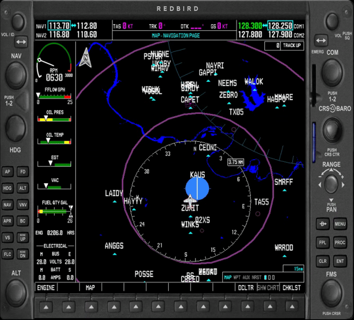
Engine Indication System (EIS)
The 1000 Engine Indication System is displayed on the left side of the MFD and includes gauges, bar graphs, and numeric readouts of engine parameters. The EIS displays all critical engine, fuel, and electrical indications. The indicators vary by aircraft, but contain all the information found in traditional engine and electrical system gauges including: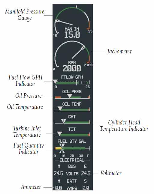
- Manifold Pressure gauge
- Tachometer
- Fuel Flow indicator
- Oil Pressure indicator
- Oil Temperature indicator
- Cylinder Head Temperature (CHT) indicator
- Exhaust Gas Temperature (EGT) indicator
- Turbine Inlet Temperature (TIT) indicator
- Fuel Quantity indicator
- Voltmeter
- Ammeter
What Can I Do with a GPS?
The GPS component of the 1000 MFD can help you to:
- Determine where you are.
- Determine where your destination is.
- Determine how to get from your current location to your destination.
- See a graphic depiction of the terrain.
- Find information about airports, intersections, NDBs, and VORs.
- Locate the nearest airport, intersection, NDB, or VOR.
- Proceed direct to any airport, intersection, NDB, or VOR.
- Follow a VFR or IFR flight plan.
- Fly instrument procedures.
- Be aware of the airspace boundaries in your vicinity.
MFD Page Groups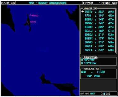
The GPS/Navigation information that appears on the MFD is presented on pages, and you can only view one page at a time. Some pages are organized into groups of related pages, called page groups. Think of page groups as chapters in a book, and pages as the pages within each chapter. There are three page groups modeled in the Redbird 1000.
The Map (MAP) page group includes:
- Navigation Map page
The Waypoint page group includes:
- Airport Information page
- Intersection Information page
- NDB Information page
- VOR Information page
The Nearest page group includes:
- Nearest Airports page
- Nearest Intersections page
- Nearest NDB page
- Nearest VOR page
Navigating the Pages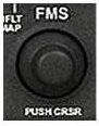
To move through the pages of the MFD you'll use the FMS knobs.
To select a page group, rotate the large FMS knob to select a page group (MAP, WPT, or NRST).
To select a page within a page group, rotate the small FMS knob.
The bottom right corner of each page provides a graphical indication of which page group and page within that group is selected:

Additionally, the selected page group and page are displayed at the top of the MFD:

You'll also use the following keys as you work with the MFD pages:
| Key | Function |
 |
Clear - Press to erase information or cancel an entry. Press and hold to return to the Navigation Map page at any time. |
 |
Enter - Press to accept a menu selection or data entry. |
 |
Menu - Press to display context-sensitive options. |
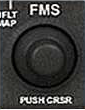 |
Cursor - Press small FMS knob to access and enter data. |
Using the Cursor
When the cursor is on, you can access and enter data in different windows
using the small and large FMS knobs, and the ENT and CLR keys.
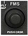
To turn on the on-screen cursor, press the small FMS knob.
To scroll down a list of choices or information, press the
small FMS knob to activate the cursor, then turn the large
FMS knob to scroll through the list.
To move the cursor on a page rotate the large FMS knob.
To select individual letters and numbers for input at the highlighted cursor location, rotate the small FMS knob.
Using the Navigation Map page
The Navigation Map page is the default MFD page and features a large
moving map display that shows:
- Airports, airspace, navaids, and land data
- An icon representing the aircraft's present position
- The aircraft's heading
To change the Navigation map scale, rotate the MFD Joystick knob.
To display topographical information on the Navigation Map:
- Press the MAP softkey.
- Press the TOPO softkey.
To display traffic on the Navigation Map:
- Press the MAP softkey
- Press the TRAFFIC softkey
To de-clutter the Navigation Map, press the DCLTR softkey.
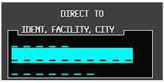
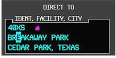
Direct-to Navigation
The 1000's Direct-to function provides a quick method of setting a course to a destination waypoint (an airport, VOR, NDB, or intersection). Once a Direct-to command is activated, the 1000 will establish a point-to-point (great circle) course line from your current position to the selected destination. The Navigation Status bar at the top of the PFD will provide steering guidance until a new destination is selected, and the CDI will indicate the direct course to the next waypoint (when GPS is selected). In addition to selecting a destination by identifier, the Direct-to page also allows you to select airports, VORs, and NDBs by facility name. You can also select a Direct-to destination from a list of the nearest airports.
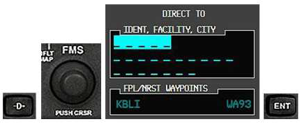
To select a Direct-to destination:
- Press the Direct-to key, then rotate the large FMS knob to highlight the Identifier (IDENT), Facility, Flight Plan (FPL), or Nearest (NRST) data fields.
- Use the FMS knobs to enter the desired destination, and press the ENT key twice to activate the Direct-to.
Re-centering the CDI needle
If you're navigating to a waypoint using Direct-to and get off course, the Direct-to function may also be used to re- center the CDI needle and proceed to the same waypoint.
 To re-center the CDI needle to the current waypoint, press the Direct-to key, followed by the ENT key twice.
The Select Direct-to waypoint page always displays the nearest airports (to your current position) in the NRST field. Navigating directly to a nearby airport is just a few simple steps away.
Direct-to Shortcuts
Shortcuts are available when using the Direct-to key, allowing you to bypass the use of the FMS knobs to enter the destination waypoint's identifier. You can set a Direct-to course from any page displaying a single waypoint identifier (such as the WPT pages for airports and navigation aids) by simply pressing the Direct-to key and then the ENT key twice. For pages that display a list of waypoints (e.g., the Nearest Airport page), you must highlight the desired waypoint with the cursor before pressing the Direct-to key.
Another tip: once you have one letter or number entered into a data field, you can type the rest of the word on your keyboard instead of having to rotate the FMS knobs. (This is not a feature of the real 1000, but it saves time when you're "twisting" with a mouse!)
Take it Slowly
If you're a bit intimidated by all there is to learn about the 1000, there's a secret: you don't have to know how to do everything to use it effectively.
Start slowly, and focus on learning to use the Primary Flight Display and Engine Indication System on easy VFR flights. Once you get comfortable flying in a glass cockpit, start playing with the MFD, explore all the page groups and pages, and start using Direct-to navigation.
Then, start planning longer flights with the Flight Simulator flight planner and fly them using the 1000. Do some reading, and when you're ready, dive into the world of glass cockpit instrument flying. That's where you'll see the 1000 really shine.
Most of all, play around, experiment, and have fun!
For questions or assistance contact Redbird Support
Legal Stuff
FCC NOTICE
This equipment has been tested and found to comply with the limits for a class B digital device, pursuant to part 15 of the FCC Rules. These limits are designed to provide reasonable protection against harmful interference in a residential installation. This equipment generates, uses, and radiates radio frequency energy and if not installed and used in accordance with the instructions, may cause harmful interference to radio communications. However, there is no guarantee that interference will not occur in a particular installation. If this equipment does cause harmful interference to radio or television reception, which can be determined by turning the equipment off and on, the user is encouraged to try to correct the interference by one or more of the following measures:
• Reorient or relocate the receiving antenna.
• Increase the separation between the equipment and receiver.
• Connect the equipment into an outlet on a circuit different from that to
which the receiver is connected.
• Consult the dealer or an experienced radio/TV technician for help.
This equipment has been certified to comply with the limits for a class B computing device, pursuant to FCC Rules. In order to maintain compliance with FCC regulations, shielded cables must be used with this equipment. Operation with non-approved equipment or unshielded cables is likely to result in interference to radio and TV reception. The user is cautioned that changes and modifications made to the equipment with out the approval of the manufacturer could void the user’s authority to operate this equipment.
COPYRIGHT
Copyright 2008 by REDBIRD Flight Simulations, Inc.
Under the copyright laws, this manual may not be copied, reproduced or distributed in any form or by any means, in whole or in part, without the written consent of the author: REDBIRD Flight Simulations, Inc. . Your rights to the software are governed by the accompanying software license agreement.
Every effort has been made to ensure that the information in this manual is accurate. REDBIRD Flight Simulations, Inc. is not responsible for printing or clerical errors.
All terms mentioned in this manual that are actually known to be trademarks or service marks are listed below. REDBIRD Flight Simulations, Inc. cannot attest to the accuracy of this information. Use of a term in this manual should not be regarded as affecting the validity of any trademark or service mark.
IBM and PC are trademarks of International Business Machines Corporation Windows 95, 98, 2000, Me, NT, XP, MS Flight Simulator X, and FSX are trade marks of Microsoft Corporation. Jeppesen is a trademark of Jeppesen Sanderson Inc. Honeywell Bendix/King KMA28, KR87 KN62A KT76C KAP 140 are registered trade marks of Honeywell Bendix/King, REDBIRD 1000SD is a trade mark of REDBIRD Flight Simulations, Inc.
LICENSE AGREEMENT
This is a license agreement and not an agreement for sale. A license agreement is a legal agreement between you, the end user (You), and REDBIRD Flight Simulations, Inc. and Microsoft "Licensors.” Please read the soft ware license agreements "Agreements" carefully before opening the sealed disk envelope. If you do not agree with the terms and conditions of this Agreement, you should return the UNOPENED disk envelope (along with all accompanying items) within 30 (thirty) days of invoice date to the company.