Basic Functions | Operations | Alerts & Annunciations | Legal Stuff | EULA
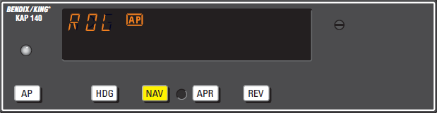
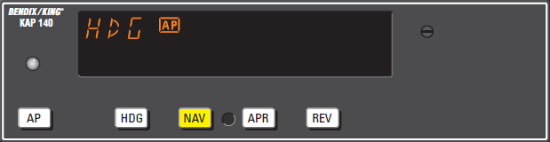
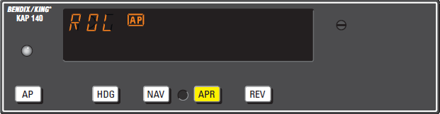
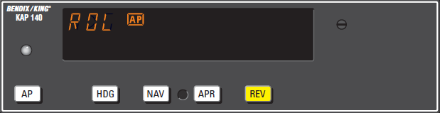
Operating Modes: ROL | HDG | NAV | APR | REV | VS | ALT
Please Note
The reader of this manual is expected to know how to fly an aircraft or to be participating in a structured and approved flight training program. This manual is in no respect a tutorial in visual flight, instrument flight or navigation. Its only purpose is to introduce the hardware and software to enable a pilot to use the system.
The information in this manual is subject to change without notice and does not represent a commitment on the part of the licensor. The software and hardware described in this document are provided under a license agreement. The software and hardware may be used or copied only in accordance with the terms of the license agreement.
KAP140 Functions
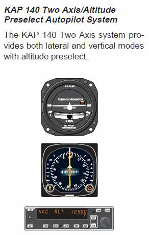
KAP 140 Two Axis with Altitude Preselect Operation
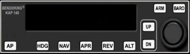
The KAP 140 is a digital, panel-mounted autopilot system for light aircraft. 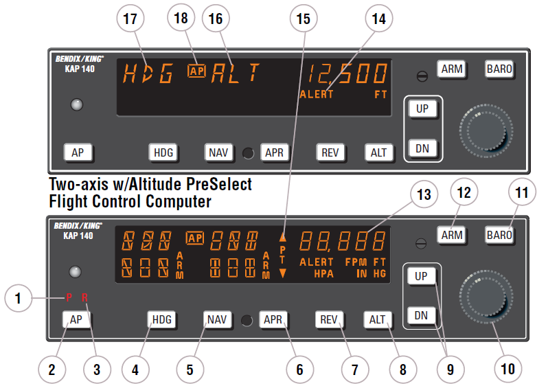
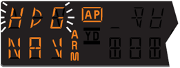
- PITCH AXIS, (P) ANNUNCIATOR
When illuminated, indicates failure of the pitch axis and will disengage the autopilot when the failure occurs and not allow engagement of the pitch axis. - AUTOPILOT ENGAGE/DISENGAGE (AP) BUTTON
When pushed, engages the autopilot if all logic conditions are met. The autopilot will engage in the basic roll (ROL) mode which functions as a wing leveler and in the vertical speed (VS) hold mode. The commanded vertical speed is displayed in the upper right corner of autopilot display area for three seconds after engagement or if either the UP or DN button is pressed. The captured VS will be the vertical speed present at the moment of AP button press. When pressed again, will disengage the autopilot. For software version 03/01 and later, the AP button must be pressed and held for 0.25 seconds to engage the autopilot. - ROLL AXIS (R) ANNUNCIATOR
When illuminated, indicates failure of the roll axis and will disengage the autopilot and not allow engagement. - HEADING (HDG) MODE SELECTOR BUTTON
When pushed, will arm the Heading mode, which commands the airplane to turn to and maintain the heading selected by the heading bug on either the DG or HSI. A new heading may be selected at any time and will result in the airplane turning to the new heading. Button can also be used to toggle between HDG and ROL modes. This button will engage the autopilot in units with software prior to software version 03/01. - NAVIGATION (NAV) MODE SELECTOR BUTTON
When pushed, will arm the navigation mode. The mode provides automatic beam capture and tracking of VOR, LOC or GPS as selected for presentation on the HSI or CDI. NAV mode is recommended for enroute navigation tracking. NAV mode may also be used for front course LOC tracking when GS tracking is not desired. - APPROACH (APR) MODE SELECTOR BUTTON
When pushed, will arm the Approach mode. This mode provides automatic beam capture and tracking of VOR, GPS, LOC, and Glideslope (GS) on an ILS, as selected for presentation on the HSI or CDI. APR mode is recommended for instrument approaches. - BACK COURSE APPROACH (REV) MODE SELECTOR BUTTON
When pushed, will arm the Back Course approach mode. This mode functions similarly to the approach mode except that the autopilot response to LOC signals is reversed, and GS is disabled. - ALTITUDE HOLD (ALT) MODE SELECT BUTTON
When pushed, will select the Altitude Hold mode. This mode provides tracking of the reference altitude. The reference altitude is the altitude at the moment the ALT button is pressed. If the ALT button is pressed with an established VS rate present, there will be altitude overshoot (approximately 10% of the VS rate), with the airplane returned positively to the reference altitude. This button will engage the autopilot in units with software prior to software version 03/01. - VERTICAL TRIM (UP/DN) BUTTONS
The action of these buttons is dependent upon the vertical mode present when pressed. If VS mode is active, the initial button stroke will bring up the commanded vertical speed in the display. Subsequent immediate button strokes will increment the vertical speed commanded either up or down at the rate of 100 ft/min per button press, or at the rate of approximately 300 ft/min per second if held continuously. If ALT mode is active, incremental button strokes will move the altitude hold reference altitude either up or down at 20 feet per press, or if held continuously will command the airplane up or down at the rate of 500 ft/min, synchronizing the altitude hold reference to the actual airplane altitude upon button release.
(Note that the altitude hold reference is not displayed. The display will continue to show the altitude alerter reference.) - ROTARY KNOBS
Used to set the altitude alerter reference altitude; or may be used immediately after pressing the BARO button, to adjust the autopilot baro setting to match that of the airplane’s altimeter when manual adjustment is required. (In some installations the baro setting is automatically synced to that of the altimeter.) - BARO SET (BARO) BUTTON
When pushed and released, will change the display from the altitude alerter selected altitude to the baro setting display (either IN HG or HPA) for 3 seconds. If pushed and held for 2 seconds, will change the baro setting display from IN HG to HPA or vice versa. Once the baro setting display is visible the rotary knobs may be used to manually adjust the baro setting if automatic baro correction is not available. - ALTITUDE ARM (ARM) BUTTON
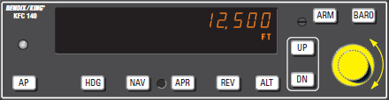
When pushed will toggle altitude arming on or off. When ALT ARM is annunciated, the autopilot will capture the altitude alerter displayed altitude (provided the aircraft is climbing or descending in VS to the displayed altitude). When the autopilot is engaged, ALT arming is automatic upon altitude alerter altitude selection via the rotary knobs. Note that the alerter functions are independent of the arming process thus providing full time alerting, even when the autopilot is disengaged. - ALTITUDE ALERTER/VERTICAL SPEED/BARO SETTING DISPLAY
Normally displays the altitude alerter selected altitude. If the UP or DN button is pushed while in VS hold, the display changes to the command reference for the VS mode in FPM for 3 seconds. If the BARO button is pushed, the display changes to the autopilot baro setting in either IN HG or HPA for 3 seconds.
NOTE: This display may be dashed for up to 3 minutes on start up if a blind encoder is installed which requires a warm up period. - ALTITUDE ALERT (ALERT) ANNUNCIATION
The ALERT annunciate is illuminated 1000 ft. prior to the selected altitude, extinguishes 200 ft. prior to the selected altitude and illuminates momentarily when the selected altitude is reached. Once the selected altitude is reached a flashing ALERT illumination signifies that the 200 ft. “safe band” has been exceeded and will remain illuminated until 1000 ft. from the selected altitude. Associated with the visual alerting is an aural alert (5 short tones) which occurs 1000 feet from the selected altitude upon approaching the altitude and 200 feet from the selected altitude on leaving the altitude. - PITCH TRIM (PT) ANNUNCIATION
A flashing PT with arrows indicates the direction of required pitch trim. A solid PT without an arrow head is an indication of a pitch trim fault. During manual electric trim operation (autopilot disengaged), detection of a stuck MET switch will be indicated by a solid PT. When the fault is corrected, the annunciation will extinguish. - PITCH MODE DISPLAY
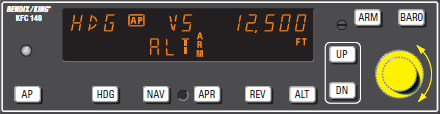
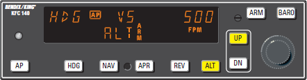
Displays the active and armed pitch modes (VS, ALT, ARM, ALT and GS). - ROLL MODE DISPLAY
Displays the active and armed roll modes (ROL, HDG, NAV ARM, NAV, APR ARM, APR, REV ARM, REV, GS ARM). Also displayed will be flashing AP annunciation (5 seconds) at each autopilot disconnect accompanied by an aural tone (for 2 seconds). - AUTOPILOT ENGAGED (AP) ANNUNCIATION
Illuminates whenever the autopilot is engaged. Flashes during pilot initiated or automatic disengagement. Only applicable for software versions 03/01 or later.
Operating Modes
Wing Leveler (ROL) Mode
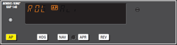
 In the roll mode, the autopilot maintains wings level flight.
- Engage autopilot - Press AP. For software version 03/01 and later, the AP button must be pressed and held for 0.25 seconds to engage the autopilot.
NOTE: The KAP 140 engages into ROL mode as a default.
Heading Select (HDG) Mode
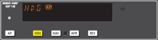
 In the heading mode, the autopilot will fly a selected heading. The following steps should be taken to operate in the heading mode:
- Move the heading “bug” to the desired heading on the DG or HSI using the Heading Select knob.
- Engage autopilot - Press AP. For software version 03/01 and later, the AP button must be pressed and held for 0.25 seconds to engage the autopilot.
- Depress the HDG button on the KAP 140 to engage the heading select mode. The autopilot will turn the aircraft in the shortest direction to intercept and fly the heading.
- If you move the heading “bug” again while the heading select mode is engaged, the autopilot will immediately turn the aircraft in the direction of the newly selected heading.
- Press HDG button again and the autopilot will return to the ROL mode.
Navigation (NAV) Mode

 Navigation (NAV) Mode Using a DG from HDG Mode (45° Intercept)
In the navigation (NAV) mode, the autopilot intercepts and tracks VOR/RNAV and GPS courses.
To arm NAV mode (with the KAP 140 currently in the HDG mode):
- Select the desired frequency for VOR or RNAV. For GPS, verify the desired waypoint or destination.
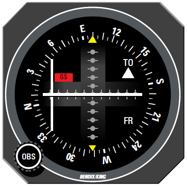
- OBS Knob - SELECT desired course.
- NAV Mode Selector Button - PRESS. Note NAV ARM annunciated.
NOTE: When NAV is selected, the autopilot will flash HDG for 5 seconds to remind the pilot to reset the HDG bug to the OBS course. Check the heading displayed on the DG against the magnetic compass and reset if necessary. - Heading Selector Knob - ROTATE BUG to agree with OBS course.

Note Instruments: CDI needle to left.
Intercept heading 45° to the left of
selected (heading bug) course. - If the Course Deviation Bar is greater than 2 to 3 dots: the autopilot will annunciate NAV ARM; when the computed capture point is reached the ARM annunciator will go out and the selected course will be automatically captured and tracked. If the D-Bar is less than 2 to 3 dots: the HDG mode will disengage upon selecting NAV mode; the NAV annunciator will illuminate and the capture/ track sequence will automatically begin.

 Navigation (NAV) Mode Using a DG from ROL Mode (All Angle Intercept)
In the navigation (NAV) mode, the autopilot intercepts and tracks VOR/RNAV and GPS courses.
To arm NAV mode (with the KAP 140 currently in the ROL mode):
- Maneuver the aircraft to the desired intercept angle prior to selecting ROL mode.
- Select the desired frequency for VOR or RNAV. For GPS, verify the desired waypoint or destination.
- OBS Knob - SELECT desired course.
- NAV Mode Selector Button - PRESS. Note NAV ARM annunciated.

NOTE: When NAV is selected, the autopilot will flash HDG for 5 seconds to remind the pilot to reset the HDG bug to the OBS course. Check the heading displayed on the DG against the magnetic compass and reset if necessary. - Heading Selector Knob - ROTATE BUG to agree with OBS course.

Note Instruments: CDI needle to left. Intercept heading 30° to the left of selected (heading bug) course. - If the Course Deviation Bar is greater than 2 to 3 dots: the autopilot will annunciate NAV ARM; when the computed capture point is reached the ARM annunciator will go out and the selected course will be automatically captured and tracked. If the D-Bar is less than 2 to 3 dots: the ROL mode will disengage upon selecting NAV mode; the NAV annunciator will illuminate and the capture/ track sequence will automatically begin.

Note: Intercept angles greater than 45° can result in course overshoot when close to the station. Therefore, intercept angles greater than 45° are not recommended.
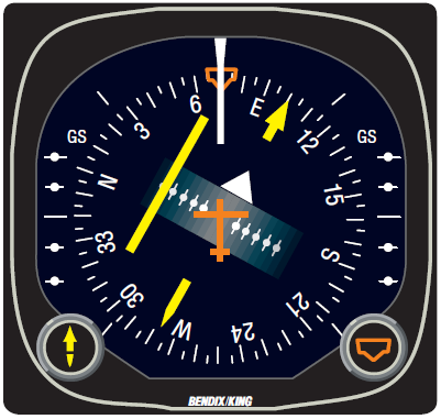 Navigation (NAV) Mode Using an HSI
In the navigation (NAV) mode, the autopilot intercepts and tracks VOR/RNAV and GPS courses.
To arm NAV mode (with the KAP 140 currently in the HDG mode):
- Select the desired frequency for VOR or RNAV. For GPS, verify the desired waypoint or destination.
- Course Bearing Pointer - SET to desired course.
- Heading Selector Knob - SET BUG to provide desired intercept angle.
- NAV Mode Selector Button - PRESS.
Note NAV ARM annunciated.
- If the Course Deviation Bar is greater than 2 to 3 dots: the aircraft will continue in HDG mode (or ROL if HDG is not selected) with NAV ARM annunciated; when the computed capture point is reached HDG will disengage, the ARM annunciator will go out and the selected course will be automatically captured and tracked. If the D-Bar is less than 2 to 3 dots: the HDG mode (or ROL if HDG is not selected) will disengage upon selecting NAV mode; the NAV annunciator will illuminate and the capture/ track sequence will automatically begin.

Note: Intercept angles greater than 45° can result in course overshoot when close to the station. Therefore, intercept angles greater than 45° are not recommended.
Approach (APR) Mode

 Approach (APR) Mode Using a DG from HDG Mode (45° Intercept)
The Approach (APR) mode allows the autopilot to intercept and track LOC, VOR/RNAV and GPS courses.
To arm APR mode (with the KAP 140 currently in the HDG mode):
- Select the desired frequency for LOC, VOR or RNAV. For GPS, verify the desired approach.
- OBS Knob - SELECT desired approach course. (For a localizer, set it to serve as a memory aid.)
- APR Mode Selector Button - PRESS. Note APR ARM annunciated.

NOTE: When APR is selected, the autopilot will flash HDG for 5 seconds to remind the pilot to reset the HDG bug to the desired approach course. Check the heading displayed on the DG against the magnetic compass and reset if necessary. - Heading Selector Knob - ROTATE BUG to agree with desired approach course.

Note Instruments: CDI needle to left.
Intercept heading 45° to the left of
selected (heading bug) course. - If the Course Deviation Bar is greater than 2 to 3 dots: the autopilot will annunciate APR ARM; when the computed capture point is reached the ARM annunciator will go out and the selected course will be automatically captured and tracked. If the D-Bar is less than 2 to 3 dots: the HDG mode will disengage upon selecting APR mode; the APR annunciator will illuminate and the capture/ track sequence will automatically begin.

 Approach (APR) Mode Using a DG from ROL Mode (All Angle Intercept)
The Approach (APR) mode allows the autopilot to intercept and track LOC, VOR/RNAV and GPS courses.
To arm APR mode (with the KAP 140 currently in the ROL mode):
- Maneuver the aircraft to the desired intercept angle prior to selecting ROL mode.
- Select the desired frequency for LOC, VOR or RNAV. For GPS, verify the desired approach.
- OBS Knob - SELECT desired approach course. (For a localizer, set it to serve as a memory aid.)
- APR Mode Selector Button - PRESS. Note APR ARM annunciated.

NOTE: When APR is selected, the autopilot will flash HDG for 5 seconds to remind the pilot to reset the HDG bug to the desired approach course. Check the heading displayed on the DG against the magnetic compass and reset if necessary. - Heading Selector Knob - ROTATE BUG to agree with desired approach course.

Note Instruments: CDI needle to left. Intercept heading 30° to the left of selected (heading bug) course. - If the Course Deviation Bar is greater than 2 to 3 dots: the autopilot will annunciate APR ARM; when the computed capture point is reached the ARM annunciator will go out and the selected course will be automatically captured and tracked. If the D-Bar is less than 2 to 3 dots: the ROL mode will disengage upon selecting APR mode; the APR annunciator will illuminate and the capture/ track sequence will automatically begin.

Note: Intercept angles greater than 45° can result in course overshoot when close to the station. Therefore, intercept angles greater than 45° are not recommended.

 Approach (APR) Mode Using an HSI
The Approach (APR) mode allows the autopilot to intercept and track LOC, VOR/RNAV and GPS courses.
To arm APR mode (with the KAP 140 currently in the HDG mode):
- Select the desired frequency for LOC, VOR or RNAV. For GPS, verify the desired approach.
- Course Bearing Pointer - SET to desired course.
- Heading Selector Knob - SET BUG to provide desired intercept angle.
- APR Mode Selector Button - PRESS. Note APR ARM annunciated.

- If the Course Deviation Bar is greater than 2 to 3 dots: the aircraft will continue in HDG mode (or ROL if HDG is not selected) with the APR ARM annunciated; when the computed capture point is reached HDG mode will disengage, the ARM annunciator will go out and the selected course will be automatically captured and tracked. If the D-Bar is less than 2 to 3 dots: the HDG mode (or ROL if HDG is not selected) will disengage upon selecting APR mode; the APR annunciator will illuminate and the capture/track sequence will automatically begin.

Note: Intercept angles greater than 45° can result in course overshoot when close to the station. Therefore, intercept angles greater than 45° are not recommended.
Back Course (REV) Mode


 Back Course (REV) Mode Using a DG from HDG Mode (45° Intercept)
The Back Course (REV) mode allows the autopilot to intercept and track a localizer back course.
To arm REV mode (with the KAP 140 currently in the HDG mode):
- Select the desired frequency for LOC.
- OBS Knob - SELECT front course inbound heading.
- REV Mode Selector Button - PRESS. Note REV ARM annunciated.

NOTE: When REV is selected, the autopilot will flash HDG for 5 seconds to remind the pilot to reset the HDG bug to the front course inbound heading. Check the heading displayed on the DG against the magnetic compass and reset if necessary. - Heading Selector Knob - ROTATE BUG to agree with the FRONT COURSE inbound heading.
 Note Instruments: CDI needle to the right. Intercept heading 45° to the left of the back course.
 - If the Course Deviation Bar is greater than 2 to 3 dots: the autopilot will annunciate REV ARM; when the computed capture point is reached the ARM annunciator will go out and the selected course will be automatically captured and tracked. If the D-Bar is less than 2 to 3 dots: the HDG mode will disengage upon selecting REV mode; the REV annunciator will illuminate and the capture/ track sequence will automatically begin.

 Back Course (REV) Mode Using a DG from ROL Mode (All Angle Intercept)
The Back Course (REV) mode allows the autopilot to intercept and track a localizer back course.
To arm REV mode (with the KAP 140 currently in the ROL mode):
- Maneuver the aircraft to the desired intercept angle prior to selecting ROL mode.
- Select the desired frequency for LOC.
- OBS Knob - SELECT front course inbound heading.
- REV Mode Selector Button - PRESS. Note REV ARM annunciated.

NOTE: When REV is selected, the autopilot will flash HDG for 5 seconds to remind the pilot to reset the HDG bug to the front course inbound heading. Check the heading displayed on the DG against the magnetic compass and reset if necessary. - Heading Selector Knob - ROTATE BUG to agree with the FRONT COURSE inbound heading.

Note Instruments: CDI needle to the right. Intercept heading 30° to the left of the back course. - If the Course Deviation Bar is greater than 2 to 3 dots: the autopilot will annunciate REV ARM; when the computed capture point is reached the ARM annunciator will go out and the selected course will be automatically captured and tracked. If the D-Bar is less than 2 to 3 dots: the HDG mode will disengage upon selecting REV mode; the REV annunciator will illuminate and the capture/ track sequence will automatically begin.

Note: Intercept angles greater than 45° can result in course overshoot when close to the station. Therefore, intercept angles greater than 45° are not recommended.


 Back Course (REV) Mode Using an HSI
The Back Course (REV) mode allows the autopilot to intercept and track a localizer back course.
To arm REV mode (with the KAP 140 currently in the HDG mode):
- Select the desired frequency for LOC.
- Course Bearing Pointer - SET to the FRONT COURSE inbound heading.
- Heading Selector Knob - SET BUG to provide desired intercept angle.
- REV Mode Selector Button - PRESS. Note REV ARM annunciated.

- If the Course Deviation Bar is greater than 2 to 3 dots: the aircraft will continue in HDG mode (or ROL if HDG is not selected) with the REV ARM annunciated; when the computed capture point is reached HDG mode will disengage, the ARM annunciator will go out and the selected course will be automatically captured and tracked. If the D-Bar is less than 2 to 3 dots: the HDG mode (or ROL if HDG is not selected) will disengage upon selecting REV mode; the REV annunciator will illuminate and the capture/track sequence will automatically begin.

Note: Intercept angles greater than 45° can result in course overshoot when close to the station. Therefore, intercept angles greater than 45° are not recommended.
Vertical Speed (VS) Mode
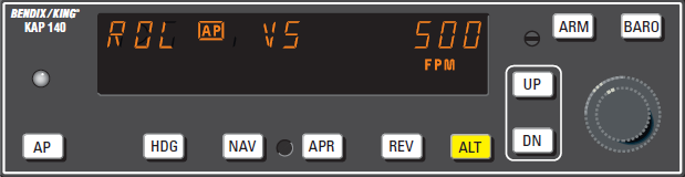
The Vertical Speed (VS) mode allows variable speed climbs and descents. The ALT button toggles between altitude hold and vertical speed modes.
Note: The KAP 140 engages into VS mode as a default.
To operate in the VS mode (with autopilot currently disengaged):
- AP button - Press. Note ROL, VS and current vertical speed is displayed. If no other modes are selected the autopilot will operate in the ROL and vertical speed hold modes. For software version 03/01 and later, the AP button must be pressed and held for 0.25 seconds to engage the autopilot.
- UP or DN button - Select desired climb or descent rate. Each button stroke will increment the vertical speed commanded up or down by 100 ft/min per button press, or at the rate of approximately 300 ft/min per second if held continuously.
- ALT button - Press. Note ALT changes to VS and current vertical speed is displayed.
- UP or DN button - Select desired climb or descent rate. Each button stroke will increment the vertical speed commanded up or down by 100 ft/min per button press, or at the rate of approximately 300 ft/min per second if held continuously.
Note: VS command value will be displayed during Control Wheel Steering (CWS) and for three seconds following VS engagement or pressing the UP or DN button. Both altitude and vertical speed utilize the same display area. Altitude is always displayed except during vertical speed selection. If the VS command value is not displayed, pressing (and releasing) the UP or DN button will not change the indicated altitude reference but will display the VS command value.
Note: When operating at or near the best rate of climb airspeed, at climb power settings, and using vertical speed hold, it is easy to decelerate to an airspeed where continued decreases in airspeed will result in a reduced rate of climb. Continued operation in vertical speed mode can result in a stall.
Altitude Hold (ALT) Mode
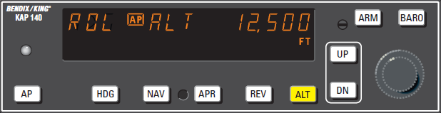
The Altitude Hold (ALT) mode maintains the pressure altitude acquired upon selection of altitude hold. The ALT button toggles between altitude hold and vertical speed modes.
To operate in the ALT mode (with autopilot currently in the Vertical Speed mode):
- ALT button - Press. Note ALT is annunciated and autopilot maneuvers to maintain pressure altitude acquired at button selection.
- UP or DN button - Select to change altitude. Incremented button strokes will move the reference altitude by 20 feet per press, or if held continuously will command a 500 ft/min altitude change, acquiring a new reference altitude upon button release.
Note: Incremented altitude changes should be limited to 500 ft. of change.
Altitude Alerting and Preselect
The Altitude Preselect function allows capturing of a desired altitude and transferring into altitude hold. Manual input of desired altitude is accomplished through the rotary knobs on the faceplate of the KAP 140.
The Altitude Alerting function will visually and aurally announce approaching, acquiring and deviation from a selected altitude.
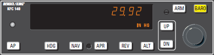
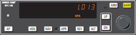
Altimeter Setting
Installations with remote baro input:
- BARO setting - CHECK. depressing the BARO button will display the baro setting for three seconds.
Installations without remote baro input:
Upon successful completion of preflight test, the baro display will flash.
- BARO setting - Enter barometri setting using the rotary knobs OR if correct as displayed, press BARO.

Baro unit conversion
The barometric pressure display can toggled between IN HG and HPA as needed by the pilot.
- BARO button - Press and hold for two seconds.
Altitude Alerter
The function of the Altitude Alerter is independent of the autopilot.
- ALTITUDE SELECT knob - ROTATE until the desired altitude is displayed.
Note: The ALERT annunciation is illuminated 1000 ft. prior to the selected altitude, extinguishes 200 ft. prior to the selected altitude and illuminates momentarily when the selected altitude is reached. Once the selected altitude is reached, a flashing ALERT illumination signifies that the 200 ft. “safe band” has been exceeded and will remain illuminated until 1000 ft. from the selected altitude. Associated with the visual alerting is an aural alert (five short tones) which occurs 1000 ft. from the selected altitude upon approaching the altitude and 200 ft. from the selected altitude on leaving the altitude.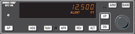
Altitude Preselect
- ALTITUDE SELECT knob - ROTATE until desired altitude is displayed. ARM annunciation occurs automatically upon altitude selection when the autopilot is engaged.
- Airplane - ESTABLISH desired vertical speed to intercept the selected altitude.
- Upon altitude capture, ALT ARM will extinguish and ALT will be annunciated.
Note: Altitude preselect captures are not recommended on non-precision approaches to capture the MDA. Glideslope coupling will preclude an altitude capture on an ILS.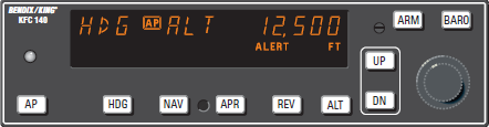
Voice Messaging
The following standard voice messages will be annunciated as conditions warrant:
- “TRIM IN MOTION, TRIM IN MOTION…” - Pitch trim running for more than 5 seconds.
- “CHECK PITCH TRIM” - An out of trim condition has existed for 15 seconds.
- Airplane Control Wheel - GRASP FIRMLY, press CWS and check for an out of pitch trim condition. Manually retrim as required.
- CWS button - RELEASE.
- AUTOPILOT OPERATION -
CONTINUE if satisfied that the
out of trim condition was temporary.
DISCONTINUE if evidence
indicates a failure of the auto trim
function.
The following optional voice messages will be annunciated if the system is configured for voice messaging:
- “ALTITUDE” - 1000 feet
before approaching selected altitude. - “LEAVING ALTITUDE” - 200
feet away, departing selected altitude. - “AUTOPILOT” - Autopilot has
disengaged, either through pilot
action or automatically.
FCC NOTICE
This equipment has been tested and found to comply with the limits for a class B digital device, pursuant to part 15 of the FCC Rules. These limits are designed to provide reasonable protection against harmful interference in a residential installation. This equipment generates, uses, and radiates radio frequency energy and if not installed and used in accordance with the instructions, may cause harmful interference to radio communications. However, there is no guarantee that interference will not occur in a particular installation. If this equipment does cause harmful interference to radio or television reception, which can be determined by turning the equipment off and on, the user is encouraged to try to correct the interference by one or more of the following measures:
• Reorient or relocate the receiving antenna.
• Increase the separation between the equipment and receiver.
• Connect the equipment into an outlet on a circuit different from that to
which the receiver is connected.
• Consult the dealer or an experienced radio/TV technician for help.
This equipment has been certified to comply with the limits for a class B computing device, pursuant to FCC Rules. In order to maintain compliance with FCC regulations, shielded cables must be used with this equipment. Operation with non-approved equipment or unshielded cables is likely to result in interference to radio and TV reception. The user is cautioned that changes and modifications made to the equipment with out the approval of the manufacturer could void the user’s authority to operate this equipment.
COPYRIGHT
Copyright 2008 by REDBIRD Flight Simulations, Inc.
Under the copyright laws, this manual may not be copied, reproduced or distributed in any form or by any means, in whole or in part, without the written consent of the author: REDBIRD Flight Simulations, Inc. . Your rights to the software are governed by the accompanying software license agreement.
Every effort has been made to ensure that the information in this manual is accurate. REDBIRD Flight Simulations, Inc. is not responsible for printing or clerical errors.
All terms mentioned in this manual that are actually known to be trademarks or service marks are listed below. REDBIRD Flight Simulations, Inc. cannot attest to the accuracy of this information. Use of a term in this manual should not be regarded as affecting the validity of any trademark or service mark. IBM and PC are trademarks of International Business Machines Corporation Windows 95, 98, 2000, Me, NT, XP, MS Flight Simulator X, and FSX are trade marks of Microsoft Corporation. Jeppesen is a trademark of Jeppesen Sanderson Inc. Honeywell Bendix/King KMA28, KR87 KN62A KT76C KAP 140 are registered trade marks of Honeywell Bendix/King, REDBIRD 1000SD is a trade mark of REDBIRD Flight Simulations, Inc.
LICENSE AGREEMENT
This is a license agreement and not an agreement for sale. A license agreement is a legal agreement between you, the end user (You), and REDBIRD Flight Simulations, Inc. and Microsoft "Licensors.” Please read the soft ware license agreements "Agreements" carefully before opening the sealed disk envelope. If you do not agree with the terms and conditions of this Agreement, you should return the UNOPENED disk envelope (along with all accompanying items) within 30 (thirty) days of invoice date to the company.