TD/TD2 6-pack Avionics Configuration
Brief descriptions of the avionics included and how they are used on a Redbird TD/TD2 with a Steam Gauge Avionics Configuration.
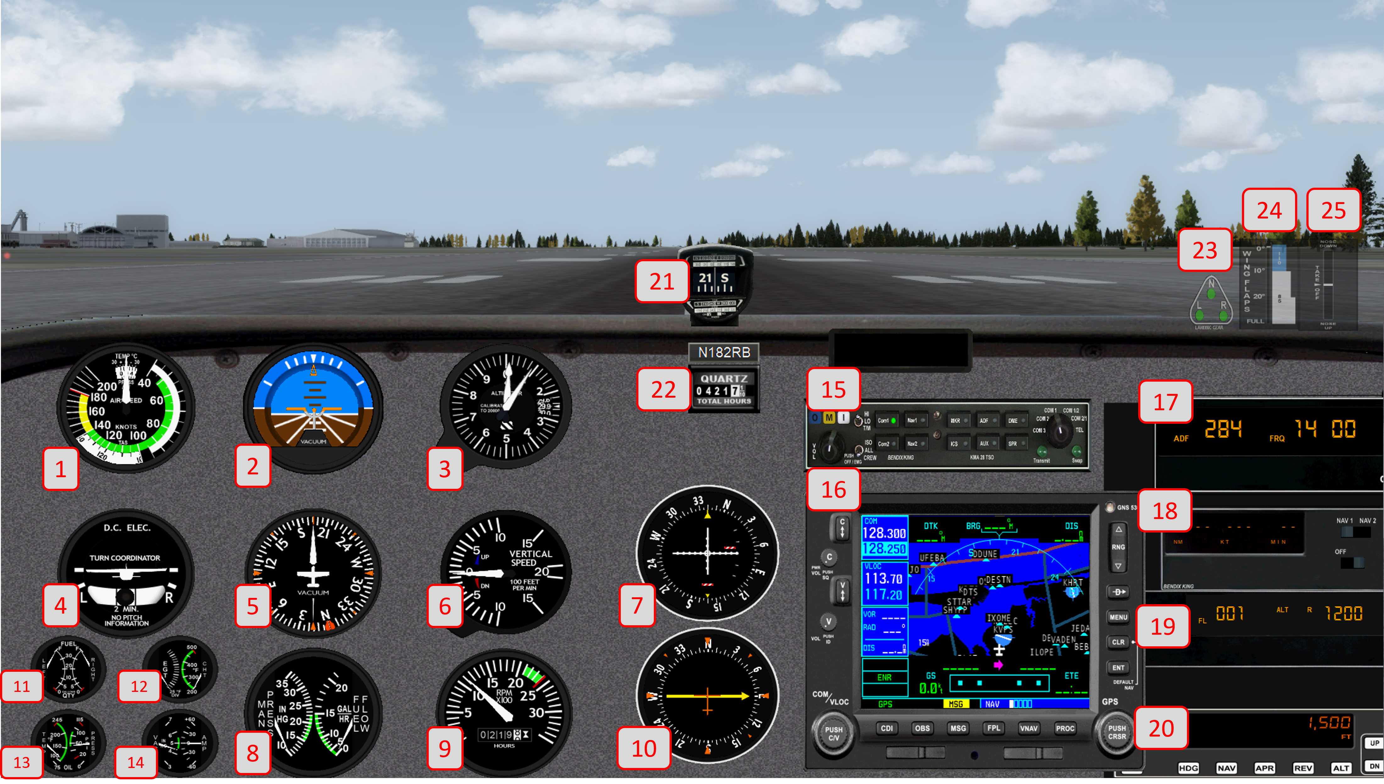
- Airspeed Indicator
- Fuel Quantity Indicator
- Exhaust Gauge Temperature & Cylinder Head Temperature
- Oil Temperature & Pressure Gauge
- Vacuum Gauge & Ammeter
- Radio Panel (modeled after KMA 28)
- GPS (modeled after GNS 530)
- ADF Panel
- DME (modeled after KN62A)
- Transponder (modeled after RB76C)
- Autopilot (modeled after KAP140)
- Whiskey Compass
- Hobbs gauge
- Landing Gear Indicator
- Flaps Indicator
- Trim Indicator
Below are brief descriptions of the avionics included and how they are used on a Redbird TD/TD2 Steam Gauge Avionics Configuration.
1. Airspeed Indicator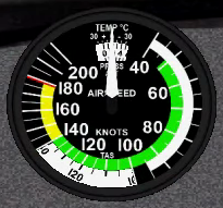
Description:
A flight instrument displaying indicated airspeed; also includes true airspeed scale.
How it's used on a Redbird:
Turn the knob to adjust for the current temperature.
2. Attitude Indicator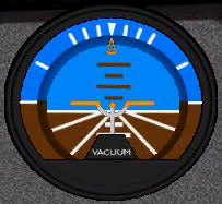
Description:
Formerly known as the gyro horizon or artificial horizon, is a flight instrument that informs the pilot of the aircraft orientation relative to Earth's horizon.
How it's used on a Redbird:
Turn the knob to adjust the bar to the horizon indicator when level.
3. Altimeter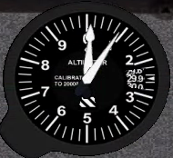
Description:
An instrument used to measure the altitude of an object above a fixed level, usually sea level when set to proper barometric pressure.
How it's used on a Redbird:
Turn the knob to adjust for the current barometric pressure.
4. Turn Coordinator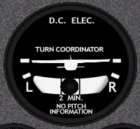
Description:
The turn coordinator (TC) is a further development of the turn and slip indicator (T/S) with the major difference being the display and the axis upon which the gimbal is mounted. The display is that of a miniature airplane as seen from behind. This looks similar to that of an attitude indicator.
How it's used on a Redbird:
The ball should be centered between the lines during coordinated flight.
5. Heading Indicator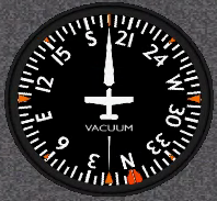
Description:
A flight instrument used in an aircraft to inform the pilot of the aircraft's heading. It is sometimes referred to by its older names, the directional gyro (DG), and also direction indicator (DI).
How it's used on a Redbird:
Turn the Left knob to adjust the card to match the whiskey compass.
Turn the Right knob to adjust the Heading Bug to the desired heading.
6. Vertical Speed Indicator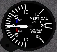
Description:
Also known as a rate of climb and descent indicator (RCDI), variometer, rate-of-climb indicator, or vertical velocity indicator (VVI) – is one of the flight instruments in an aircraft used to inform the pilot of the rate of descent or climb.
How it's used on a Redbird:
No active pilot participation is required to use this device.
7. VOR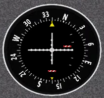
Description:
VHF Omnidirectional Range instrument used to determine direction to/from a VOR transmitter. Also used to perform instrument approaches, including glideslope information when applicable.
How it's used on a Redbird:
Tune NAV1 radio to desired VOR or ILS frequency. Turn OBS knob to select desired radial or heading.
8. Manifold Pressure & Fuel Flow Indicator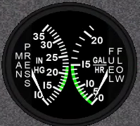
Description:
The manifold pressure gauge is an engine instrument typically used in piston aircraft engines to measure the pressure inside the induction system of an engine.
The Fuel Flow Indicator indicates the engine's fuel use in Gallons per hour.
How it's used on a Redbird:
No active pilot participation is required to use this device.
Manifold Pressure gauge is only available on TD2 systems by enabling the "High Performance" setting during startup.
9. RPM Indicator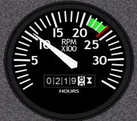
Description:
Measures the engine's revolutions per minute, and how many hours the tachometer has been used above a certain RPM level.
How it's used on a Redbird:
No active pilot participation is required to use this device.
10. ADF 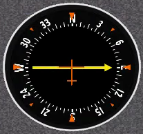
Description:
Automatic Direction Finder indicates the bearing to a non-directional beacon or other radio source transmitting in the HF or MF frequency ranges (MF frequencies are basically the same as AM radio frequencies).
How it's used on a Redbird:
Tune the ADF Panel to an appropriate frequency, and the needle on the ADF should activate. Turn the knob to select desired radial or heading.
11. Fuel Quantity Indicator
Description:
Reflects quantity of fuel in gallons remaining in each wing tank.
How it's used on a Redbird:
No active pilot participation is required to use this device.
12. Exhaust Gauge Temperature & Cylinder Head Temperature
Description:
Indicates exhaust temp and cylinder head temp in degrees Fahrenheit.
How it's used on a Redbird:
No active pilot participation is required to use this device.
Cylinder Head Temperature gauge is only available on TD2 systems by enabling the "High Performance" setting during startup.
13. Oil Temperature & Pressure Gauge
Description:
Indicates engine oil temp in degrees Fahrenheit and oil pressure in pounds per square inch.
How it's used on a Redbird:
No active pilot participation is required to use this device.
14. Vacuum Gauge & Amp Meter
Description:
Indicates force of vacuum pump in inches of mercury, and charge/discharge state of the alternator/battery system in Amperes.
How it's used on a Redbird:
No active pilot participation is required to use this device.
15. Radio Panel (modeled after KMA 28)
Description:
Indicates pilot radio selections and allows pilot to select which radios to monitor and from which to transmit, adjust volume, etc...
How it's used on a Redbird:
Refer to KMA 28 usage guides online for a comprehensive set of instructions on the use of this device.
16. GPS (modeled after GNS 530)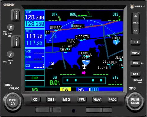
Description:
A highly-integrated GPS navigation unit designed to inform and assist the pilot in navigation, planning, and monitoring navigational duties.
How it's used on a Redbird:
Refer to GNS 530 usage guides online for a comprehensive set of instructions on the use of this device.
17. ADF Panel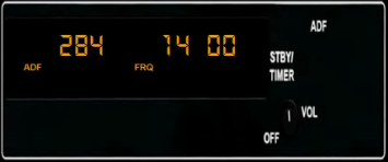
Description:
Automatic Direction Finder Panel provides information and timing services to assist pilots in navigation with the ADF.
How it's used on a Redbird:
Tune to an appropriate frequency using the dual-rotary knob, then activate using the FRQ/<-> button. FLT/ET & SET/RST buttons are used to view and interact with the built in clock/timer.
18. DME (modeled after KN 62A)
Description:
Distance Measuring Equipment (DME) is a radio navigation technology that measures the distance between an aircraft and a ground station.
How it's used on a Redbird:
Tune and activate NAV1 to an appropriate frequency, and the DME should activate.
19. Transponder (modeled after RB76C)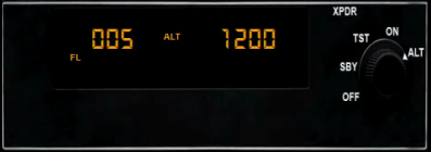
Description:
Transponder provides identification, position, and altitude information to air traffic control via radio.
How it's used on a Redbird:
Refer to RB76C usage guides online for a comprehensive set of instructions on the use of this device.
20. Autopilot (modeled after KAP140)
Description:
Allows pilot to turn over stick and rudder flying duties to a robust computer processor that is capable of some flying tasks, including performing instrument approaches in coordination with other onboard navigation equipment.
How it's used on a Redbird:
| AP | Turns the Autopilot on/off |
| HDG | Toggles Heading mode |
| NAV | Toggles NAV mode |
| APR | Toggles Approach mode |
| REV | Toggles Reversionary mode |
| ALT | Toggles Altitude-hold mode, or Vertical Speed mode |
| UP | Controls desired vertical speed when in Vertical Speed mode |
| DN | Controls desired vertical speed when in Vertical Speed mode |
| ARM | Used in conjunction with APR/ALT buttons to arm the autopilot to change modes |
| BARO | Press after setting the barometric pressure |
Refer to the Redbird KAP140 Supplement Guide, or other KAP140 usage guides online for a comprehensive set of instructions on the use of this device.
21. Whiskey Compass
Description:
A traditional magnetic compass.
How it's used on a Redbird:
Used to verify and correct procession errors in the heading indicator, and as a backup to the heading indicator.
22. Hobbs Gauge
Description:
The Hobbs Gauge is a totalizer that indicates the total time the simulator has been running, in hours and tenths of an hour. On Redbird systems, the Hobbs Gauge is running whenever the simulation software is running (whether in a "paused" state or actively flying).
How it's used on a Redbird:
No active pilot participation is required to use this device.
23. Landing Gear Indicator
Description:
The landing gear indicator reflects the position and safety of the landing gears.
| Green | Down & Locked |
| Red | In Transit |
| White/Off | Up & Locked |
How it's used on a Redbird:
Lift the landing gear lever to stow the gear during flight; lower the handle to lower the gear prior to landing.
Retractable Gear is only available on TD2 systems by enabling the "Retractable Gear" setting during startup.
24. Flaps Indicator
Description:
Flaps indicator displays how far down the flaps are deployed in degrees of deflection relative to the chord of the wing.
How it's used on a Redbird:
Move the flaps handle up and down to adjust the flaps (and this indicator).
25. Trim Indicator
Description:
The trim indicator displays how far up or down the elevator trim tab is positioned.
How it's used on a Redbird:
Move the trim wheel or electric trim rocker switch to adjust the trim tab (and this indicator).