
Before You Begin
This document pertains to the TD/TD2 platform both with and without the Horizon Kit. Please make sure that you are referencing the correct steps when assembling.
CAUTION
If you are installing a Horizon Kit on your TD/TD2, due to the added weight of the additional monitors, the 3-monitor upgrade must be installed on a Redbird TD table or a Redbird TD Platform.
Things to know prior to installation
- You will need a sturdy, solid table with a maximum tabletop thickness of 2.25” including rails and the underlying structure.
- There must be at least 29” between the legs.
- If you are not installing your TD/TD2 on the optional Redbird TD Table, you must install the adjustable supporting leg.
- Some hand tools are required for installation. Hand tighten only, and do NOT use power tools as they may lead to damage.
- Do not power on any part of your TD/TD2 until the unit is fully assembled.
- Lift all items from both sides using correct lifting techniques. Seek assistance when lifting larger items.
- Retain all original packaging and shipping materials.
- Any unauthorized software on your Redbird TD/TD2 is prohibited and will void your warranty.
If Installing the Horizon Kit
- Requires the new TD/TD2 monitor setup with removable acrylic panels.
- Requires two (2) people to move once assembled on the table.
- Requires a #2 Phillips screwdriver. (Not included)
- Unit requires 4 outlets - a power strip may be required. (Not included)
- Requires cutters for the cable ties. (Not included)
What’s in the box
TD/TD2
- A — Monitor
- B — Acrylic Panel
- C — Lower Switch Panel
- D — Keyboard
- E — Speakers
- F — Panel Thumb Screws
- G — Computer
- H — Thumb Screws
- I — HDMI Cables + Display Port to HDMI Adapters
- J — Adjustable Supporting Leg (Optional)
Horizon Kit (Includes all TD/TD2 materials listed above, plus the following items)
- A — Support Screws
- B — Monitor Screws
- C — Monitor Wing Support Brackets
- D — Monitor Support Block
- E — Horizon Monitors
- F — Monitor Power Cables
- G — 5-32” Allen Wrench
Step 1 : Position the Lower Switch Panel and Optional Supporting Leg if Needed
Lower Switch Panel
- Slide the lower switch panel onto the table. You can slide it to the left of the table to maximize room for two seats/pilots at the table, which is ideal for schools.
- Hand-tighten the (4) thumbscrews to ensure secure clamping of the lower switch panel to the tabletop. The panel should be firmly secured and fixed into place. Tighten only as much as need to prevent movement. Do not over-tighten as this may cause damage.
- PRO TIP: When tightening table clamps, lift up on lower to reduce sag.
Installing the Optional Supporting Leg
- Not required if installed on optional Redbird TD Table.
- Position the Adjustable Supporting Leg under the threaded opening at the bottom right hand corner of the Lower Switch Panel. (See Fig. 2)
- Hand-tighten the leg so that it is fully secured to the Lower Switch Panel.
- To adjust the Adjustable Supporting Leg height, twist the lower portion of the leg until the foot pad has reached the floor. Hand-tighten the wing nut to secure the leg.
Step 2 : Connect Monitor Cables
For TD/TD2 Without Horizon Kit
- Connect the monitor cable (HDMI) to the center monitor.
- Insert the power cable.
For TD/TD2 With Horizon Kit
- Connect the monitor cable (HDMI w/ HDMI to DP adapter) to the center monitor.
- Insert the power cable.
PRO TIP:
Plug in the power and monitor cables before continuing.
Step 3 : Position the Monitor
For TD/TD2 Without Horizon Kit
- Position the Monitor on top of the Lower Switch Panel, so that the holes are aligned.
- Pass the (4) loose thumbscrews through the aligned holes to attach the Monitor and Lower Switch Panel.
- Hand-tighten the thumbscrews so that the Monitor is fully secured.
For TD/TD2 With Horizon Kit
- Position the Monitor on top of the Lower Switch Panel, so that the holes are aligned.
- Pass four (4) Support Screws through the aligned holes to attach the Monitor and Lower Switch Panel.
- Firmly tighten.
Step 4 : Attach Center Support Block
(For Horizon Kit Only - If you are not installing the Horizon Kit, skip to step 7)
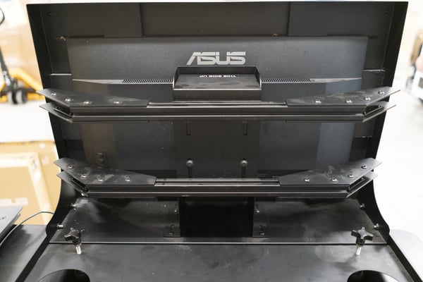
- Place center support block and framework as shown below. Make sure block is positioned with the correct side up (see sticker on block).
- Pass four (4) Support Screws through the aligned holes to attach the Monitor and Lower Switch Panel.
- Firmly tighten.
PRO TIP:
If the screws do not go in smoothly, do not force it, as there is a risk of cross threading. They should go in very smoothly.
Step 5 : Connect Monitor Wings
- Loosen wing hardware screws. Make sure that no threads of the screws are protruding through the bracket. (See image below)
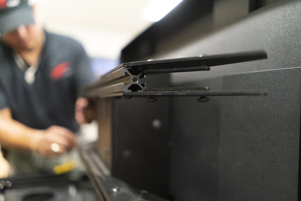
- Lift the lower screw brackets up slightly to help guide the wing.
- Insert each wing with monitor plate facing pilot (see image below). Slide them in until they are physically stopped.
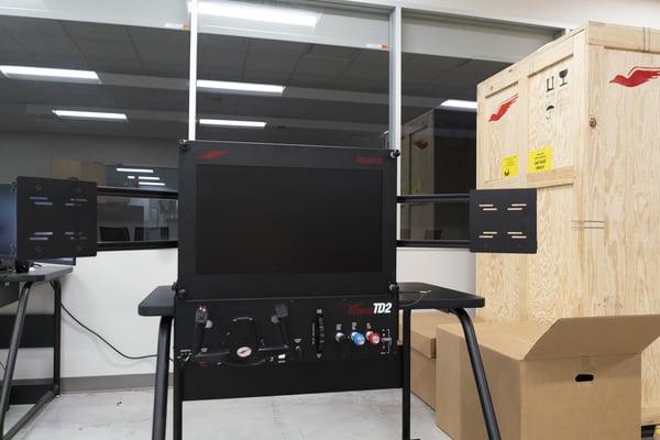
- Firmly tighten all screws on each wing after all arms are in place.
Step 6 : Install the Horizon Monitors
Have a helper hold the monitors during installation.
- Hold the monitor in place. It should touch the center TD monitor.
- Insert screws and secure the monitor to the mount.
- Repeat with other monitor.
- Firmly tighten all screws (8 total).
Step 7 : Position the Computer
For TD/TD2 Without Horizon Kit
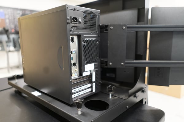
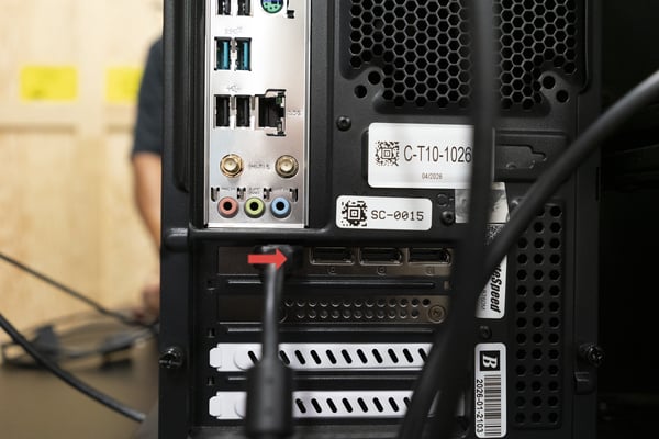
- Plug HDMI cable from the monitor into the far left HDMI port on the computer. (see image)
- Plug the monitor power cable into a standard wall outlet.
For TD/TD2 With Horizon Kit
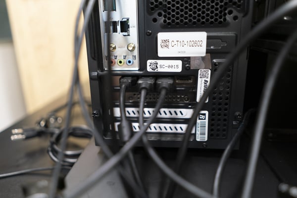
- Plug center monitor HDMI cable into the far left HDMI port on computer.
- Plug the left monitor HDMI cable (using the display port adapter) into the next port, to the right of the center monitor cable.
- Plug the right monitor (using the display port adapter) into the next plug.
Step 8 : Attach and Connect the Acrylic Panel
- Slide the Acrylic onto the four screws on the monitor frame.
- Hand-tighten the thumbscrews so the Acrylic is fully secured.
- On the bottom left corner of the back of the monitor, plug a USB cable into the USB port on the Acrylic. Plug the other end into the USB port on the back of the computer.
PRO TIP:
USE A BLACK USB PORT (not blue) ONLY FOR THE ACRYLIC CONNECTION
Step 9 : Connect Lower Switch Panel to Computer
- The Lower Instrument Panel USB cable connections will be located on the back of the Computer. Look for the USB ports that are similar in shape.
Step 10 : Connect Keyboard, Rudder Pedals, and Speakers
- Plug the keyboard into any available USB slot.
- If using rudders, plug into any BLACK USB slot
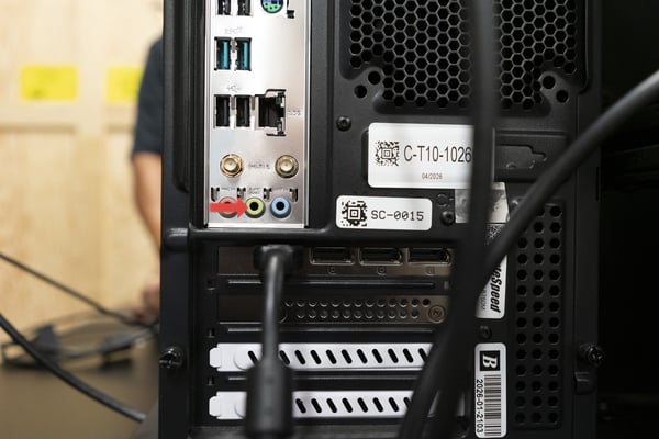
- Speaker connections will be located on the back of the computer. Plug the cable with a green band around the jack into the green audio port. See image below.
Step 11 : Connect Computer Power Cable
- Plug power cable into back of computer.
- Plug opposite end into a standard wall outlet.
Step 12 : Power on the Redbird TD/TD2
- Power on the computer. The power button is located on the lower right side near the front of the computer.
- The sim will turn on and the Redbird Navigator main menu will appear on the monitor after a few moments.
Installation Complete
Thank you for choosing Redbird Flight.